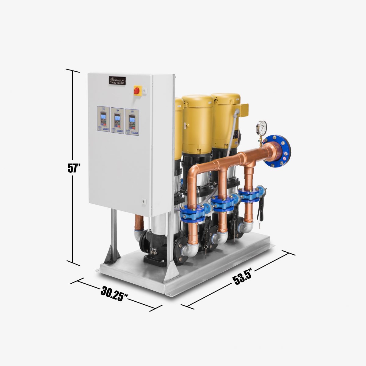
Callaghan Pump and Controls builds pump packages and we do so with real estate and space constraints in mind. We build a domestic water booster system more compact and quieter than anybody else’s system on the market. We design systems not just in New York City but we build systems for any building in any state, or any country in the world. As long as you have AC power, we can build a system for 60 Hertz as in USA or 50 Hertz as in other countries. -regardless, we build packages as tight and as close as we can possibly make them.
To deal with the noise issue, we do prefer using Ebara pumps because they seem to have the least amount of noise complaints. When you move water you will make noise. How much noise and if is it going to be a concern is always a big question. While I have documented cases where our pump systems are a full two numbers quieter than the majority of our competitors, we find it doesn’t hurt to wrap the pump end of our systems in the 1-1 ½” black soft foam rubber. This really helps to quiet the noise down. Whatever pump system is used, it should have all the headers (the suction and discharge pipes that carry all water into and out of a booster system) wrapped in insulation not just for noise but also to help with condensation.
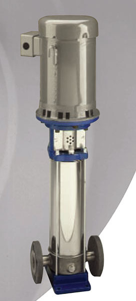
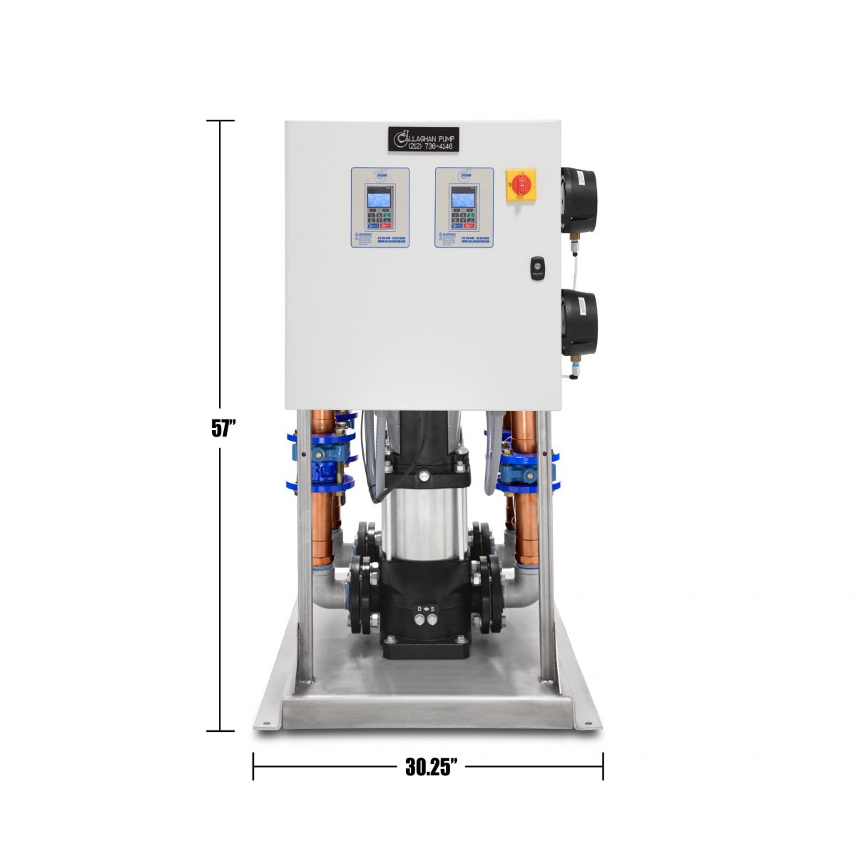
We manage the space issue by building compact packages. When we build our package, the diameter of the pump when using a vertical multi-stage is established by flow. The larger your flow, the larger the diameter of the vertical multi-stage pump. To determine your flow you need to determine your usage- and we can calculate exactly how many gallons per minute your building will need. You just need to tell us exactly what will be in the building that uses water: number of kitchen sinks, number of toilets, number of dishwashers, number of washing machines, number of showers and baths, number of utility and slop sinks, number of bars, etc. — anything that uses water– you tell us. Once flow is established, for example 100 gallons per minute is very common, you next need to determine how much pressure is desired for your domestic water system. We speak of pressure in terms of either foot of head or PSI. So if you want 100 gallons per minute and you are boosting the pressure 40 pounds your pump might be 40” tall. If you need 250 PSI discharge, your pump might be 5 feet tall. While you can use the same pump in each circumstance, the higher PSI will require more impellers to move the water and, therefore, will be taller/longer and the horse power requirements do increase, but we are still able to keep the system on the same size stainless steel base. In this way we provide our customers with the quiet and compact packages they are looking for.