Directions for Installing Sensing Lines in Jockey and Fire Pump Systems


Both fire pump system and jockey pump control panels get their run signal the exact same way through a half inch non-ferrous pipe commonly referred to as a sensing line.

Sensing lines should be piped the exact same way on both the fire and jockey pumps.


Installation of Sensing Lines in Fire Pump Systems


The concept is for the fire and jockey pump control system to sense the pressure through the use of 2 orifices(commonly drilled into ½ “check valves) on each sensing line at a distance of a minimum of 5 feet separation which will reduce water hammer which can damage the electronic transducer and the controller. Each orifice should be drilled into the two check valves on each sensing line for a total of 4. The orifices should be 3/32 inch holes drilled into check valves. These valves should be installed in these pipes without damaging the device used to change water pressure into an electronic signal. The arrow on the check valve must face away from the control panel.

The old method was to connect the sensing lines to mercoid switch, but as you can tell by the name this contained mercury, which is no longer allowed. The manufacturer came out with a mechanical non-mercury switch, but while they were inventing this switch, technology surpassed them and transducers are now the approved method of converting water pressure to an electronic signal. The majority of fire pump control panel manufacturers use electronic transducers to sense pressure. Jockey pump control panels are a little more liberal because jockey pumps are not directly required by code. But the code also states that you cannot use the fire pump to maintain system pressure– therefore, unless you plan to use gravity to maintain pressure, you need the jockey pump even though the code does not require it since system pressure needs to be maintained.

Sizing the jockey pump is a simple procedure.  It is strictly 1% of the fire pump’s flow and 110% of the fire pump’s pressure.

Transducers use a small rubber diaphragm, a spring, and an extremely small circuit board which converts the position of the spring to an electronic signal. If the spring is compressed, the pressure is high and if it is relaxed the pressure is low. But because transducers do more than turn the pump on and off, we can also scale the amount of spring compression to give us an effective pressure read out. While these transducers represent a change in fire protection, the method of how we send the system’s pressure to them has not changed. The method of piping to the transducer is the same as it was for the old mercoid style.

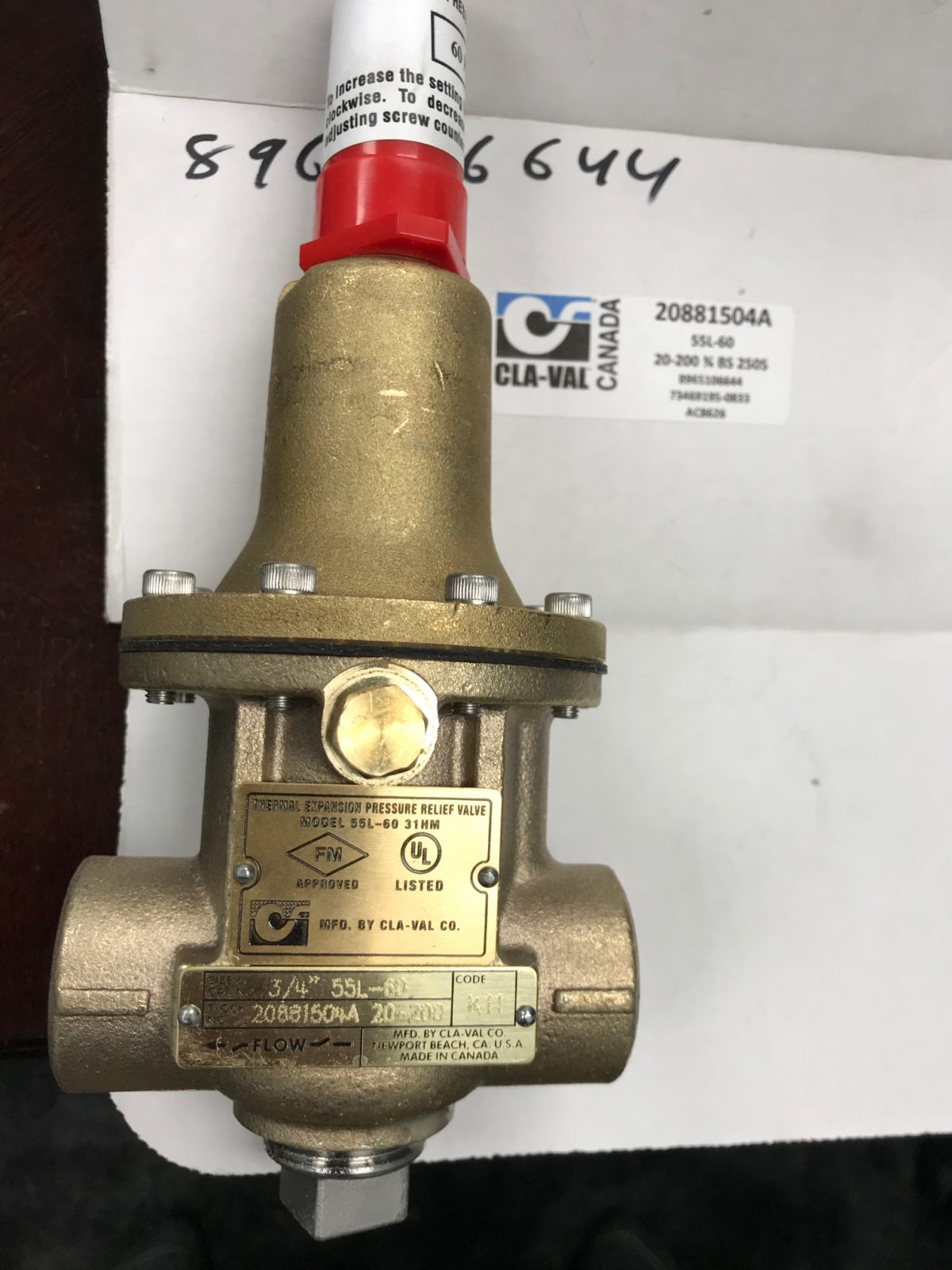
The first part is understanding that the jockey pump and the fire pump need to be located on the high-pressure side of the fire pump piping. Generally, the layout will be the pump suction or inlet, the pump discharge or outlet, and then you must pipe onto the fire pump discharge piping a ¾ “casing relief valve. This valve needs to be piped into the discharge side of the fire pump, but it must be installed before the fire pump check valve. If you pipe it after the fire pump check valve it will continue to pump water until the discharge pipe equals the same pressure as the valve was adjusted to.  The new casing relief valves that Aurora Pumps uses, Cal-Val Model 55L, are absolutely spectacular. L stands for UL which designates a valve used specifically for fire pump use and is insured for the same purpose. Please note that there is an arrow on this valve which indicates the direction of flow. The arrow points to the drain, not to the pipe.

Do not install any isolation valves on this relief valve. If the valve drips, clean it. You can service it by closing the main isolation valves.  If it does not seal completely anywhere in its adjustment range, you must repair it (kits are available) or replace it. It is very important that the discharge of this valve be piped down 3-6 inches into a funnel if an air gap is required or below the pump room drain. Make sure the drain cover or screen has a hole in it so this drain from the valve doesn’t spray all over the place. People get upset when their basements flood. I have seen flooded basements more than once, most recently to the tune of $30,000 in damages. The valve is doing its job when it is dumping water and if it is not piped correctly it can cause flooding and possibly significant resulting damage.


Checklist for Installation of Sensing Lines in Jockey and Fire Pump Systems


  • Both fire pump and jockey pump sensing lines are piped exactly the same with separate connections.
  • Non-ferrous material is used for the sensing line (bronze, stainless, or copper).
  • Both lines have 2 orifices drilled into check valves at least 5 feet apart
  • Size of the orifice in check valves is 3/32 inch
  • Arrows on check valves point away from the control panel
  • Size of sensing lines are ½”
  • Jockey pump is installed on the high pressure side of the fire pump piping.
  • Fire pump is installed on the high pressure side of the fire pump piping.
  • A ¾” casing relief valve has been installed on the discharge side of the fire pump before the fire pump check valve.
  • The direction of the arrow on the casing relief valve is pointing towards the drain.


Domestic Water Pump Sizing and Pressure Needs

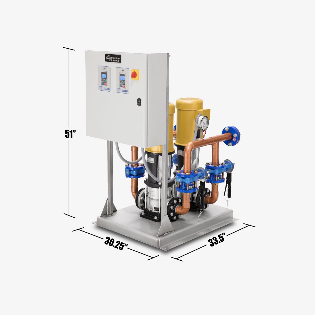
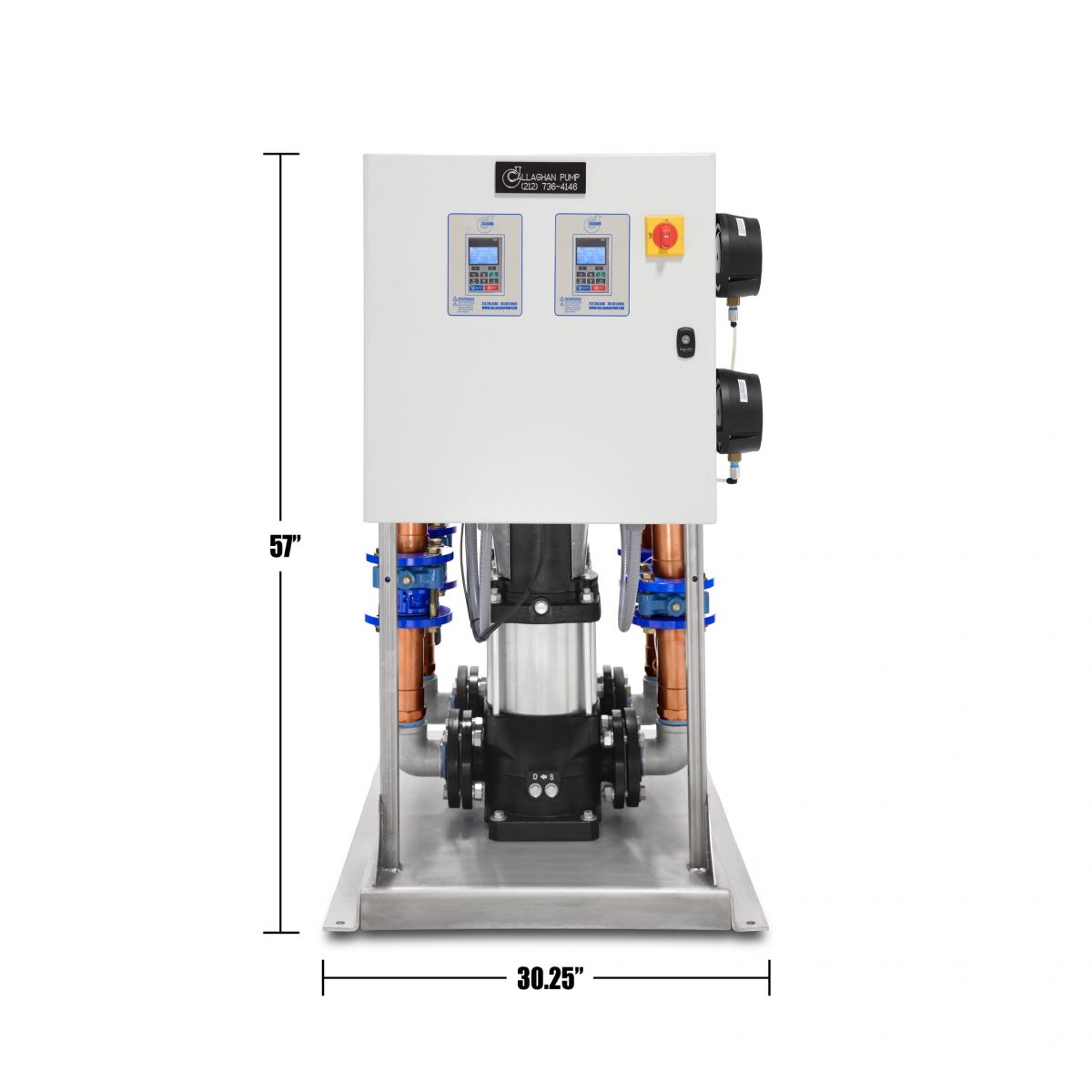
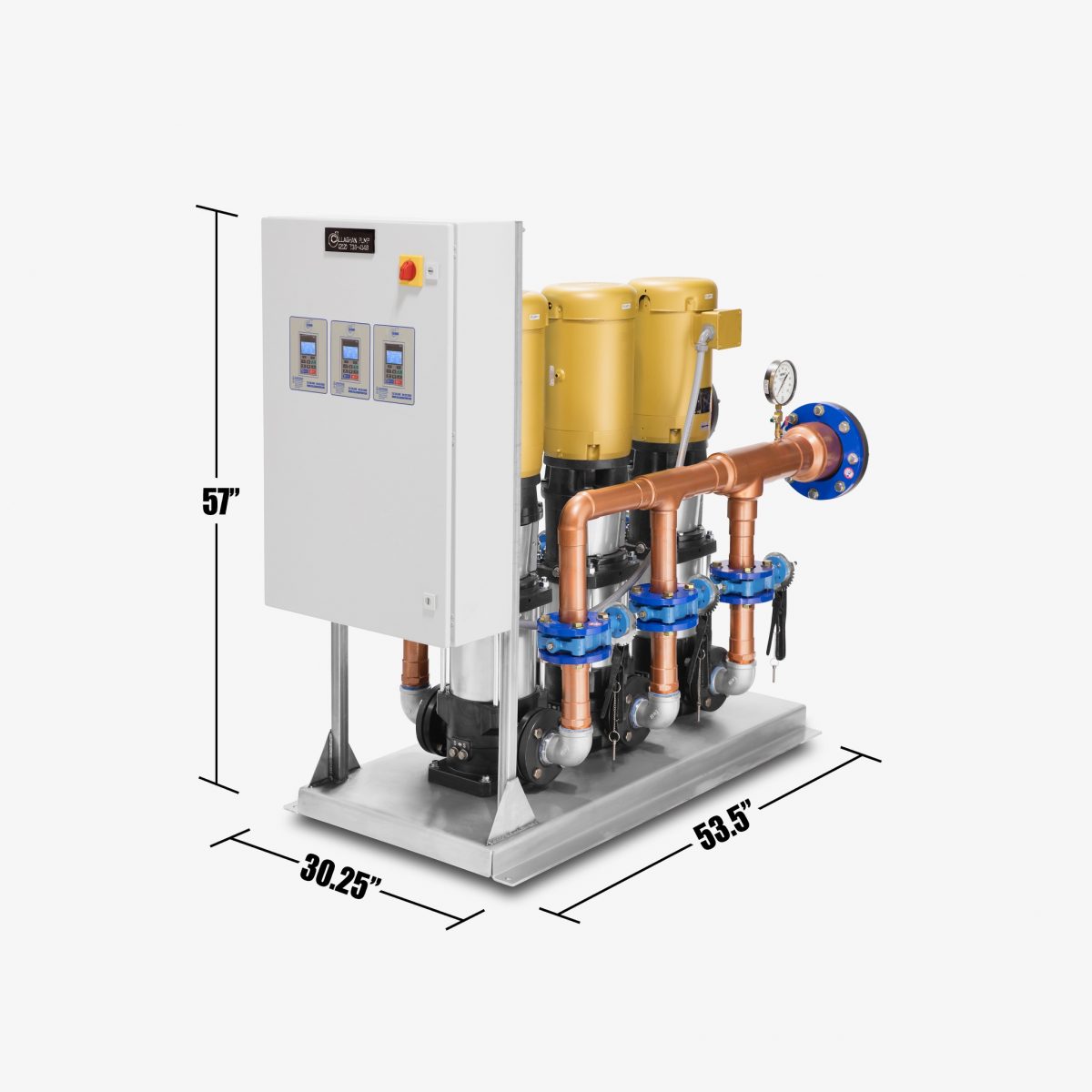
If you ask us at Callaghan Pump and Controls what physical size your pump system will be, we try to keep our package systems as compact as can be. On a standard 1 horsepower up to and including 15 horsepower systems with flows anywhere from 10 gallons/minute to 200 gallons/minute, we can build a duplex system. Our ¼” thick stainless steel base is 30.25’ wide by 36” long. That duplex system includes two pumps, a metal stainless steel stand for the control panel that comes installed, suction and discharge copper headers. The system automatically comes with loss of prime shut down, low suction pressure shut down, and high system pressure shut down. So if the pump is discharging 80 pounds and your street pressure were to go up to 80 for some reason, your pump would not run as it will let street pressure flow through it while you save the electricity. You can change pressure at a click of a button and, if,  for some reason, you feel you might be adding to the existing building you can order a duplex on a triplex base. So you will have three spots for three pumps, but right now while the building is still small and you only need two pumps. The extra space provides you with the ability to add the third pump in the future as your pumping needs increase. There is usually always room in the control panel for another drive mount. Especially in New York City, we make the system as small as possible as real estate is at a premium.

I don’t know of anyone who makes a more compact triplex domestic water booster system (a package with three pumps on the skid). The header can be 2”, 3”, 4”, 6’; header size depends on flow. The more flow, the larger the suction and discharge pipe. The easy way to remember sizing is 2” is good to 200 gallons/minute, 3” is good to 300 gallons/minute and so on. There is a chart that we can share with you if you call Callaghan Pump. While we are located in Hackensack, New Jersey, we do 90% of our sales to the 5 boroughs of Manhattan. Coincidentally, that also seems to be the area where the majority of tall buildings are located in our country. So it has been an ideal location for our company learning very quickly about what works and does not work in a highrise building. This is not to say that our systems would not work just as well in a low rise building.  

Administrators of low rise hotels and other two – three-story buildings often question why they need a pump — the answer is that it comes down to volume. Unless you run a 12” water main in from the street, chances are that you will need a booster pump; if you have any more than 30 apartments, you will need to boost the pressure up or run very large pipe in from the street. A lot of times, you look at the price of copper or stainless steel piping and if you can save $100,000 on the pipe, it pays to put in a $15,000 pump system. So why not do it? They are certainly easy to maintain; parts are readily available anywhere. All major pump manufacturers have a pump that will bolt right down to our skid. Should these pumps ever cause you problems, parts and pumps from the major players in the industry will fit. We use very simple methods for our control system; they all operate off of ¼ “ female national pipe thread(NPT). You first install a ¼” ball valve to isolate any transducers that might require replacing 10-20 years down the road. You then put in either a T or a transducer. You can either put the transducer on the header or run the wire into the Callaghan Pump Domestic Water Booster System control panel.  Customers in NYC, the Bronx, Brooklyn, Queens, often prefer them inside the control panel;  you just have to remember to drill a ¼” hole in the bottom corner of the electrical control panel so that if water were to ever leak in, it will then have an easy method to drain out of the control panel.

Callaghan Pump and Control has over 900 systems in the 25 miles radius of Times Square.  We have very few, if any, premature losses or breakdowns. This claim is based upon the idea that we consider 50,000 hours to be the standard run time for our equipment. The motor bearings are roughly the same. If you go with our standard 5 horsepower system, we always keep everything in stock to service these systems: we have transducers, we have variable speed Yaskawa drives– Model IQ Pump 1000,  and we always have motors.

Call Callaghan Pump and Controls any time you like for a free quotation.

Domestic Water Booster Systems by Callaghan Pump

Callaghan Pump and Controls builds pump packages and we do so with real estate and space constraints in mind.  We build a domestic water booster system more compact and quieter than anybody else’s system on the market. We design systems not just in New York City but we build systems for any building in any state, or any country in the world.  As long as you have AC power, we can build a system for 60 Hertz as in USA or 50 Hertz as in other countries. -regardless, we build packages as tight and as close as we can possibly make them.


To deal with the noise issue, we do prefer using Ebara pumps because they seem to have the least amount of noise complaints.  When you move water you will make noise.  How much noise and if is it going to be a concern is always a big question. While I have documented cases where our pump systems are a full two numbers quieter than the majority of our competitors, we find it doesn’t hurt to wrap the pump end of our systems in the 1-1 ½” black soft foam rubber.  This really helps to quiet the noise down. Whatever pump system is used, it should have all the headers (the suction and discharge pipes that carry all water into and out of a booster system) wrapped in insulation not just for noise but also to help with condensation.


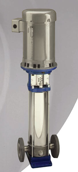
We manage the space issue by building compact packages. When we build our package, the diameter of the pump when using a vertical multi-stage is established by flow. The larger your flow, the larger the diameter of the vertical multi-stage pump. To determine your flow you need to determine your usage- and we can calculate exactly how many gallons per minute your building will need.  You just need to tell us exactly what will be in the building that uses water: number of kitchen sinks, number of toilets, number of dishwashers, number of washing machines, number of showers and baths, number of utility and slop sinks, number of bars, etc. — anything that uses water– you tell us. Once flow is established, for example 100 gallons per minute is very common, you next need to determine how much pressure is desired for your domestic water system.  We speak of pressure in terms of either foot of head or PSI. So if you want 100 gallons per minute and you are boosting the pressure 40 pounds your pump might be 40” tall. If you need 250 PSI discharge, your pump might be 5 feet tall. While you can use the same pump in each circumstance, the higher PSI will require more impellers to move the water and, therefore, will be taller/longer and the horse power requirements do increase, but we are still able to keep the system on the same size stainless steel base. In this way we provide our customers with the quiet and compact packages they are looking for.

Basic Rotations of Pump Control System

When starting any pump or working with any pump control system, whether the pump be a VFD pump, or an HVAC pump in New York being driven by a drive or an across-the-line starter, it is very important to know the basics first. Number one, make sure the water is onto the pump. If the pump and motor are coupled in the middle, called flexible coupled, make sure the two are aligned. You must make sure that motor end and the pump end are between 5-7 thousandths aligned directly to each other through this at least with a dial indicator, if not laser. When you do an alignment, you must make sure the pump is installed, that water is in the pipe, that the pump has been settled. Do the alignment and then grout the base.

The very next step would be to check the rotation of the pump. In New York City, we were sent to 15 different Manhattan mini-storage units to make sure that pumps were being tested properly. 3 of the 15 pumps that were in operation for over 20 years were running backwards. These same pumps “passed” their flow test. In reality, they did not pass the test; they were not being tested correctly. Callaghan Pump does not lie on our tests of pumps and pump control systems. Pumps either pass or fail; we don’t cheat. Many companies either do not know how to test properly, or fill out the paperwork from the previous year and send it on.

Always make sure rotation is correct, that’s vital. If it is a fire pump, and you get rotation set correctly, you must check if there’s a transfer switch. Make sure the pump rotates the correct direction when it is being fed by the generator, the backup power. These are the basics for all VFD driven pumps. You can change rotation in the drive itself; there is no need to change the wires. This is true of Yaskawa drives; it’s a simple, fast fix. If you are using a starter, you have to physically change two wires. With regards to fire pumps, once you set the rotation and tell the controller the rotation is correct if the power supply gets cut or is hooked up backwards, it will set a phase reversal alarm. These are just a few basics of pump control systems. There are many others. We will follow up in future articles.

Fire Booster Pump Systems – Some Key Aspects You Must Know

When it comes to fire booster pumps in New York City or any city, all fire pumps rely on two features to simplify matters–  a jockey pump and sensing line. The jockey pump keeps the fire pump system pressurized.  It is what does the work all of the time. If you have leaks, and you will, the jockey pump fills the system back up. It is very simple to size a jockey pump.  It is sized 1% of the fire pump’s flow. If the fire pump runs at 1000 gallons a minute, your jockey pump is 10 gallons a minute. The pressure of the jockey pump should be 110% of the fire pump’s pressure. So if you have a 1000 gallon a minute fire pump at 100 PSI, your jockey pump is sized at 10 gallons a minute at 110 PSI. No exceptions, no reason to go bigger. You do not want bigger. You do not want your jockey pump fighting the fire.

The second key feature of the fire booster pump system is the half inch sensing line going from the high-pressure side of the fire suppression line to the fire pump controller. This sensing line needs to be non-ferrous– brass or copper- and it needs to have two check valves or orifices 3/ 32” large. 3/32” is a very small hole for a reason you don’t want a half inch pressure going into a control panel should the diaphragm to break on the pressure transducer or the burden to break inside a Mercury pressure switch. You only need to sense the pressure in order to trigger the fire pump to start. Those two orifice check valves or orifices of any kind with a 3/32” hole in them need to be five feet apart. The two check valves or orifices are needed to stop any kind of water hammer when the pump shuts off, you don’t want the pressure bouncing and slamming up against the pressure transducer that could cause it to rupture and fail. Make sure, if you use a check valve, the arrows face away from the controller. Also, make sure that the check valves are at least five feet apart and the hole that you drill in the flapper 3/32 inches. Clean it out before you put it in — the small chips can clog the hole. When you tie into the fire pump controller bring your sensing line in so that it Ts up to the controller The bottom of the T should have a valve and a gage, then a valve,  then a plug –this is where you test your fire pump.

Aurora Fire Pump Necessities for Fire Pump Package Systems

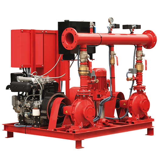
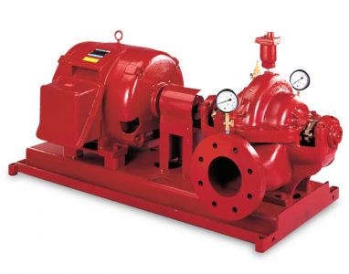
This article is not merely limited to Aurora Fire Pumps but it also applies to all brands of fire pumps including: Peerless, Patterson, Allis Chalmers, etc. Customers need to know many different things about their fire pump systems, but when it comes every Aurora Fire Pump package system or individual Aurora pump parts, it is very important to remember two main points.  

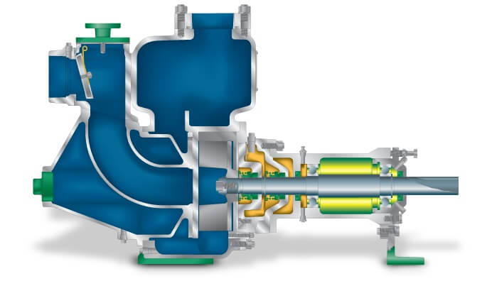
First and foremost, please remember, all fire pumps, no matter the manufacturer- Peerless, Patterson, Aurora, Allis Chalmers, etc., that are horizontal split case or vertical in-line must have packing.  Therefore, they drip all of the time. The packing is made up of several different materials but now they are non asbestos. Most fire pumps will have six rings of packing. If it is a horizontal split case there will be six rings of packing on both sides of the shaft and in order to keep the shaft lubricated water needs to drip past the shaft to keep it lubricated. When people  such as maintenance crews, etc. are inside the building, they see the drip and think that something is wrong. Often to fix what they perceive to be a leak, they will tighten down the bolts until the leaking stops.  That is absolutely wrong. You want 15- 40 drips per minute on each side of the fire pump. If it is an Aurora horizontal split case, packing will be on each side. If it is an Aurora vertical in-line fire pump, it will have packing on one side(the top side where the packing drips out).  Typically, when someone notices the fire pump leaking it is when the drain lines clog up. So it is preferable to blow out or vacuum the lines every three months or so. You get a lot of scaling and a lot of general dirt and dust that clog the drain lines.  It is recommended then that these drain lines be cleared out regularly.

The second point to remember when dealing with fire pumps is to remember that when a fire pump starts automatically it never stops until you press the red stop button on the front of the control panel. This is a new code that resulted after a fire occured in which only one sprinkler head was set off.  The pump satisfied pressure quickly so it shut down; the pump never restarted once the fire started up again. So that is why the code was changed. Fire pumps start automatically and stop manually now. You stop the pump by pressing the red round button on the panel. If you let go and it starts again, you either have a leak or a fire. Be very careful not to hold the disconnect lever down, because in the event there is a fire, you will be taking the fire protection away from the building.

These necessities apply to all fire pumps — Aurora Fire Pumps, Peerless Fire Pumps, Patterson Fire Pumps, Allis Chalmers Fire Pumps, etc.   

Sizing of a Jockey Pump for an Aurora Fire Pump System

The way to size a jockey pump for any fire pump system is the same no matter who the manufacturer is– Aurora or Peerless or Patterson, etc.  It does not matter who the makes it, the method of sizing the pump is the same. This applies to all systems.  For some reason some engineers believe that the larger the system the larger the jockey pump will need to be.

However, it is important to remember that the manner in which you size the jockey pump remains the same.  Simply stated sizing is 1% of the fire pump’s flow and 110 % of the fire pump’s head. For example, if the Aurora Fire Pump System  which is selected is rated 500 gallons per minute at 100 psi, the jockey pump needs to handle 5 gallons per minute at 110 psi. You can go slightly over or under this formula depending on what your exact pump curve can do. I would not do any less than 4 gallons per minute and I wouldn’t go any higher than 7 gallons a minute. The main reason is that you do not want the jockey pump fighting the fire; you want the fire pump fighting the fire.  

When it comes to pressure, the jockey pump needs to be able to do 10% higher than the fire pump. Adjustment of the Aurora Fire Pump System to  set up permanent operation is very simple. You run the fire pump at full speed with your suction pressure. So if the fire pump is rated 100 psi typically when it is running at shut off, meaning no water is being flowed, you might be 10% or 15% higher than that; this is called “no flow pressure,” the pressure when the pump is not flowing water.  Let’s say for this example suction pressure is 40 pounds and the pump’s rated maximum pressure is 110 psi. When you run the fire pump at full speed, the discharge pressure will be 150 psi. That is the pressure where you want your jockey pump to stop. The Aurora jockey pump should start 10 pounds less than that number. Again this does not just apply to the Aurora Fire Pump line.  It applies to every fire pump on the market.  If the maximum rated pressure of the fire pump is 110 pounds and you have 40 pounds coming in from the street, churn pressure is 150 pounds. The jockey pump stops at 150 and starts at 140.  You try to have the fire pump start 10 pound less which would be 130. Typically, you would program a stop pressure. It does not mean the fire pump is going to stop at that pressure; rather it means if the pressure is above that number the stop button will work.  So in this example, the jockey pump stops at 150 psi, starts at 140 psi, the fire pump starts at 130 and at pressures over 131 the stop button will work. That is how you size and program an Aurora Fire Pump System with jockey pump.

Variable Speed Tank Filled Domestic Water Pump Systems

Callaghan Pump manufactures its own variable speed domestic water pump systems for New York City.  They also build, program, and test variable speed tank fill systems as well. We use the exact same construction for our variable speed domestic water pumps as we do for our variable speed tank filled pumps. One might ask why we use a variable speed control when filling a tank.  Isn’t that normally a simple on/off control system? The answer is yes and no.

There is a new code in New York City that says any roof tank that is exposed to the elements that has water in it for domestic water or fire protection needs to be monitored  heated at some points during the year. Concern arises if the heating source ever breaks for some reason. You need to monitor the temperature of the water every day that the outside temperature is 40 degrees or below. Using a  variable speed system facilitates these needs because in tying in a transducer it can monitor levels and temperatures for the tank (one transducer handles all levels – low level, high level, pump 1 run, pump 2 run- meaning lead pump, lag pump, high level). Built into the transducer is a temperature sensor which not only allows you to monitor the daily temperature but also allows you to track the history.  It gives as many data points as you would like as it is able to measure the temperature every minute, every hour, or every six hours — however the user want to set it up.

The Callaghan Pump variable speed tank filled system has another benefit. If it is a large system, 15- 100 stories, when the tank is filled, the old constant speed systems stop quickly and can experience a very large “hammer” on the check valve.  The old fix was to put in a tank fill valve which starts the pump against a closed valve, then slowly opens the valve, fills the tank and, when the tank is filled, slowly closes the valve, and shuts off the pump. All of those steps are eliminated with the Callaghan Pump Variable Speed tank filled system. You can digitally determine, by standing next to the pump, the speed at which pump slows down and the check valve stops/closes.  For example, if you determine that happens at 43 hertz you can slow the pump down to 46 hertz and then very slowly slow the pump down little by little until the check valve gently touches and then you can continue to slow the pump down at a more rapid rate of speed. To do this we use the Yaskawa iQ1000 drive – you simply switch the drive from reading psi to reading of feet of head or water in the tank. It is that simple.

Stainless VFD Booster Pump System

If you are thinking about installing a variable speed domestic water pumping system or tank fill system in New York City, or any other city you must first consider the core parts. The base should be stainless steel. Steel bases rust out in a matter of years and then the pumps are no longer stable. Take a look at the base: does it have holes to be filled with grout? This would be the best choice. Some people take stainless steel bar stock and make a base out of it, but this is nowhere near as sturdy as a solid plate, quarter-inch stainless which is all Callaghan pump uses for all of our variable speed pump systems.

Secondly, the header. Most plumbers love working with copper; all of our headers are copper and stamped with “NSF”, which means no lead. If they ever have an issue where they want to add something, any plumber can work with copper. While stainless steel looks nice, it’s very difficult to work with and most plumbers do not have the capability.

Next would be pumps. You can use cast-iron pumps, stainless steel pumps, or any other type so long as it does not have lead. If you’re dealing with low flow and high head, multistage pumps work very well. If it’s something where it’s 100 gallons a minute and 100 feet of head, you might want to stick with a single stage pump and suction style because of the fewer impellers and fewer moving parts.

Lastly, the controller. Always insist on a smart drive. no matter who makes it. Smart drive means you’re not going to require a PLC, or in other words, a third-party brain. Someone needs to program PLC‘s, and people’s experience and skill working with them vary. When you buy a smart drive from a company like Yaskawa, you’re dealing with thousands of people in engineering and 20 to 30 people in technical support. There’s a lot of knowledge and a lot of back up support programs that they write in these drives today that will be serviceable in 15 years, even 20 years. Most rotating equipment last 50 to 80,000 hours. If you’ve gotten that long out of it you certainly have done very well, but the key (again): the fewer parts you have the better off you’ll be.

Callaghan Pump’s systems have: stainless steel base, copper headers, the pump of your choice so long as it’s lead free, a control panel with a through the door, interlocked handle disconnect switch, two circuit breakers (one per drive), two Yaskawa variable speed drives, and two transducers. If one transducer were to fail, it sends an alarm and starts reading the second transducer. Everything is a complete independent redundancy. You can lose one drive, one pump, one circuit breaker and the other will work completely independently of the other. you do not have to rely on a flip-flop relay or any other logic to make it switch.

Aurora Fire Pump Casing Relief Valve Installation

When it comes to any fire pump or fire pump system, whether it be Aurora, Peerless, Allis Chalmers, Patterson, etc, this rule applies to the installation of any fire pump system. All systems will need a casing relief valve. For purposes of illustration, I will be referring to the Aurora Fire Pumps because these are the systems that we sell at Callaghan Pump.

On the discharge of any fire pump, in this case the Aurora Fire Pump, you must install ¾ inch casing relief valve. The casing relief valves that Aurora supplies are manufactured by Cla-Bal, Model 55L — the letter L stands for UL approved–these valves come with insurance from Underwriters Laboratory which contributes to their cost. They are all bronze with a stainless steel ball and a stainless steel seat. They are the only ones that I have used in the past 25 years that actually reseats once it has blown off. So many of the other cheap valves have a rubber seat. As soon as they pop, the rubber is ripped and they never reseal.

This valve must be adjusted so that when the fire pump is running at churn or shut off (meaning water is not being discharged anywhere and it is running at full speed). The valve must dump; meaning it must open and flow water to a drain. Don’t just pipe this to the top of a drain. Either put it inside a funnel with an air gap or cut a hole in the top of the strainer and put the pipe three inches down into the drain. Otherwise you can flood your basement with water flying everywhere. You want a good solid 10 gallons/minute coming out of this valve, sometimes 15 gallons/minute if it is a large pump. This prevents the pump from turning the water inside the casing to steam. I have seen pump rooms that have gotten so hot they actually popped off a sprinkler head in the fire pump room. It was during construction. The sprinkler head sprayed water into the fire pump motor and into the fire pump control panel. That is why these need to be installed and they need to be installed after the fire pump discharge but before the check valve.

There is a flow direction on the valve — be sure the flow is pointed towards the drain and the drain line is piped up into to either a funnel or below the level of the strainer on a floor drain. If you do it above, it will splash everywhere, flood the basement, and cause significant damage.